Appreciate the insight! Definitely agree on the interlock.IMO, if you connect the vehicle to your panel and you do not have some sort of interlock, if the power happens to return when your vehicle is attached to your panel, your vehicle will lose. In addition, it could catch fire. Backfeeding a panel with this vehicle, IMO, is not advisable. I have over 33 years in the electric industry…
Navigation
Install the app
How to install the app on iOS
Follow along with the video below to see how to install our site as a web app on your home screen.
Note: This feature may not be available in some browsers.
More options
You are using an out of date browser. It may not display this or other websites correctly.
You should upgrade or use an alternative browser.
You should upgrade or use an alternative browser.
2400W Power Inverter
- Thread starter Vault
- Start date
- Moderator
- #62
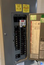
Pretty much that's to prevent you from back feeding the power lines and killing a lineman. Pole transformers step down the line voltage to 110v per leg (two legs 110v per = 220V), when you back feed your panel with 110v, the transformer doesn't know the difference and steps it up to 660v (not sure on the exact voltage) and energizes line, someone working on that line could be electrocuted. Perfectly safe IF you throw the main breaker, which severs the pole transformer. I believe it's illegal in just about every state, to back feed a breaker box without manual lockout device or an auto-disconnect device. 1st Picture above has a manual lockout device (currently not locked out).I just read this. Heads up @agjake01
Last edited:
Exactly, thanks for sharing the why. This was a pretty easy/clean install, albeit my brother helped me and knew what he was doing. Maybe $250 in parts and it worked like a charm with my 2300w Ryobi Inverter Generator (after lockout). I was able to run everything on the panel except for the oven and the AC. HW, heat etc are gas so just the igniter and blower to keep those going.Pretty much that's to prevent you from back feeding the power lines and killing a lineman. Pole transformers step down the line voltage to 110v per leg (two legs 110v per = 220V), when you back feed your panel with 110v, the transformer doesn't know the difference and steps it up to 660v (not sure on the exact voltage) and energizes line, someone working on that line could be electrocuted. Perfectly safe IF you throw the main breaker, which severs the pole transformer. I believe it's illegal in just about every state, to back feed a breaker box without manual lockout device or an auto-disconnect device. 1st Picture above has a manual lockout device (currently not locked out).
Sure would have been nice if Toyota had set up the inverter like Ford did with the Lightning.
My exact thinking. I live in Houston and have to deal with hurricanes and ice storms...I could see a usage. If you have unreliable power, and lots of outages, better than buying a generator if you already have a land cruiser to fulfill this.
- Moderator
- #65
One thing to keep in mind is that the LC 110v system is not going to run your entire house period! It will run some lights keep the fridge running etc..... but you're not drying any clothes (as it's 220v)and unless you have a very efficient washer, you're not washing clothes. Probably be able to watch TV........ IF you have an aerial antenna, maybe the cable box, but odds are if the power is out, so is the cable.
Most breaker boxes have two busses (both are 110v) and every other breaker is on the "A" buss..... example #1 breaker is on A, #2 breaker is on B, #3 is on A etc......... So being that you're only supplying one buss with 110V, you will have to move some (what you deem as critical) breakers to the powered buss. Now if you keep track of what is turned on and off it is manageable. ie.... if the fridge is running, all the lights are on, you're watching TV and you try the microwave.......... you going to pop the breaker.
The bottom line....... unless you know what you are doing, consult an electrician!
Understood. All I would hope to run would be a fridge, few LED lights, TV, antenna (maybe internet), and a portable AC. If it could be connected to my house panel that would be great but I guess I could live with running extension cords. It would be a survival mode situation and not business as usual.One thing to keep in mind is that the LC 110v system is not going to run your entire house period! It will run some lights keep the fridge running etc..... but you're not drying any clothes (as it's 220v)and unless you have a very efficient washer, you're not washing clothes. Probably be able to watch TV........ IF you have an aerial antenna, maybe the cable box, but odds are if the power is out, so is the cable.
Most breaker boxes have two busses (both are 110v) and every other breaker is on the "A" buss..... example #1 breaker is on A, #2 breaker is on B, #3 is on A etc......... So being that you're only supplying one buss with 110V, you will have to move some (what you deem as critical) breakers to the powered buss. Now if you keep track of what is turned on and off it is manageable. ie.... if the fridge is running, all the lights are on, you're watching TV and you try the microwave.......... you going to pop the breaker.
The bottom line....... unless you know what you are doing, consult an electrician!
- Moderator
- #67
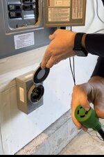
Best check the portable A/C for wattage requirements. In our case, not from the LC (yet), but I run a 12 gauge extension cord from our Honda generator to power the fridge, a few lights, and the gas fireplace if winter.Understood. All I would hope to run would be a fridge, few LED lights, TV, antenna (maybe internet), and a portable AC. If it could be connected to my house panel that would be great but I guess I could live with running extension cords. It would be a survival mode situation and not business as usual.
Correcting my Victron isolation transformer comment. The 3600W unit could not be powered by the vehicle's inverter. The smaller 2000W unit would be the unit to try.
$400 and simple to test before a full install onto a backup generator connection. But perhaps not worth it for people who have the more common 50 amp 240V generator connection. The LC inverter output can be converted with additional hardware to 240V split phase but there's no scenario where that would be a good use of money. Not enough watts available to power home 240V stuff.
$400 and simple to test before a full install onto a backup generator connection. But perhaps not worth it for people who have the more common 50 amp 240V generator connection. The LC inverter output can be converted with additional hardware to 240V split phase but there's no scenario where that would be a good use of money. Not enough watts available to power home 240V stuff.
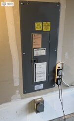
The 2000w would work well for my panel and application. I’ve already installed a 30A inlet box and plug, and I’m only planning to power 120V fuses on the panel with my generator/LC as the 240V (oven & AC) draw too much (leaving those alone).Correcting my Victron isolation transformer comment. The 3600W unit could not be powered by the vehicle's inverter. The smaller 2000W unit would be the unit to try.
$400 and simple to test before a full install onto a backup generator connection. But perhaps not worth it for people who have the more common 50 amp 240V generator connection. The LC inverter output can be converted with additional hardware to 240V split phase but there's no scenario where that would be a good use of money. Not enough watts available to power home 240V stuff.
I’ll probably wait a bit to see what others decide, but I think the Victron would be a good addition.
The 2000w would work well for my panel and application. I’ve already installed a 30A inlet box and plug, and I’m only planning to power 120V fuses on the panel with my generator/LC as the 240V (oven & AC) draw too much (leaving those alone).
I’ll probably wait a bit to see what others decide, but I think the Victron would be a good addition.
Also, rather than the 2000w transformer, I would think you’d want the 3600w so as to allow the inverter to pass through all 2400w at load.
Current doesn't pass through as a circuit. The shore side, which connects to the LC inverter, has a 3600W transformer that creates a magnetic field. The 3600w unit would trip on the 120V 20 amp circuit protection in the inverter.Also, rather than the 2000w transformer, I would think you’d want the 3600w so as to allow the inverter to pass through all 2400w at load.
There are literally no wires, if desired, between the two sides of an isolation transformer. Just a magnetic field. So the only thing the LC inverter is powering, literally, is a toroidal transformer.
I assume it does not consume a steady 2000 watts regardless of load on the house side. If that constant consumption was how it worked it would be very inefficient, but it is sold as efficient. So while my high consumption concern is unlikely I would like to better understand how the load side affects the transformer and the shore side/LC inverter.
Thanks for explaining, I was reading up on how the magnetism works - this makes sense now. Seems like the transformer would work, I’m just not sure I want to be the guinea pig though…Current doesn't pass through as a circuit. The shore side, which connects to the LC inverter, has a 3600W transformer that creates a magnetic field. The 3600w unit would trip on the 120V 20 amp circuit protection in the inverter.
There are literally no wires, if desired, between the two sides of an isolation transformer. Just a magnetic field. So the only thing the LC inverter is powering, literally, is a toroidal transformer.
I assume it does not consume a steady 2000 watts regardless of load on the house side. If that constant consumption was how it worked it would be very inefficient, but it is sold as efficient. So while my high consumption concern is unlikely I would like to better understand how the load side affects the transformer and the shore side/LC inverter.
ALL of that, went right over my head..Current doesn't pass through as a circuit. The shore side, which connects to the LC inverter, has a 3600W transformer that creates a magnetic field. The 3600w unit would trip on the 120V 20 amp circuit protection in the inverter.
There are literally no wires, if desired, between the two sides of an isolation transformer. Just a magnetic field. So the only thing the LC inverter is powering, literally, is a toroidal transformer.
I assume it does not consume a steady 2000 watts regardless of load on the house side. If that constant consumption was how it worked it would be very inefficient, but it is sold as efficient. So while my high consumption concern is unlikely I would like to better understand how the load side affects the transformer and the shore side/LC inverter.
- Moderator
- #74
The transforming has to do with the windings in the transformer. In layman terms: Imagine a hollow iron square the L/H side of the square is wrapped with 100 turns of wire and the R/H side is wrapped with 50 turns of wire, when X voltage/amperes is applied to the L/H side coil it produces a magnetic field that magnetic field is passed through the iron circle to the R/H side coil and produces X amount of electricity. Increase or decrease the amount of turns on either side and it will change the output.(it's actually a little more complicated than that but you get the idea). There are modern electronic transformers out there and I'll admit I'm not well versed on those.
Me too.ALL of that, went right over my head..
Hoping either a EE or commercial electrician shows up. Someone spam MIT with Land Cruiser brochures.
I’m afraid that an MIT electrical engineer’s explanation would still go right over my head.Me too.
Hoping either a EE or commercial electrician shows up. Someone spam MIT with Land Cruiser brochures.
Can confirm.There’s an option that pops up on the dash to turn off that feature so it doesn’t shut off.
Demo on youtube -
Not really accurate.Current doesn't pass through as a circuit. The shore side, which connects to the LC inverter, has a 3600W transformer that creates a magnetic field. The 3600w unit would trip on the 120V 20 amp circuit protection in the inverter.
True current does not pass through on wires.
The primary side (shore) has a winding that creates a magnetic field.
The secondary (output) side has a winding that absorbs the magnetic field and produces a current which in this application would be a 1:1 ratio.
Not true that the 3,600 watt transformer would by its existence trip the overcurrent protection in car. It depends on the load you put on it. If you have less than 2,400w on output it will take less than 2,400w on input. (Not counting negligible losses)
It would work perfectly fine to have an oversized transformer as long as the load is managed within the limit. Agjake is right that you would want the oversized transformer to be able to use the full 2400w.
I am not a land electrician, but I am an ABYC certified marine electrician, and Victron dealer. In my world, any newly derived source of power (inverter, generator, or transformer) needs to have the neutral and ground bonded at that source. But on boats we don’t put a permanent N-G bond at the main elec panel on board.
I believe the issues people are seeing when trying to feed a house are because of multiple separate N-G bonds which can be dangerous.
I wonder if the LC 120v output is GFI\ELCI protected. Seems like it should be and a N-G connection on the load (house) would immediately trip a GFCI as dangerous fault current will immediately be evident flowing on Ground conductor.
Apparently this Youtuber damaged her older generation Land Cruiser by dual sourcing a Jackery from a solar panel and the vehicle inverter. New products like the Ecoflow Delta 3 advertise the ability to leverage multiple simultaneous inputs (AC, DC, Solar panels etc.) to increase charging speed and diversify power sources. So I thought this might be interesting in case anybody has thoughts on what happened and how to avoid similar issues on new Land Cruiser 250s.
I fried my car with a Jackery with a portable battery solar generator
I fried my car with a Jackery with a portable battery solar generator
Similar threads
- Replies
- 38
- Views
- 3K
- Replies
- 6
- Views
- 2K
- Replies
- 7
- Views
- 635