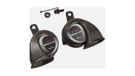
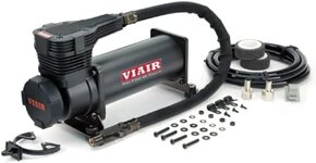
Air Compressor Mod: Pic A/C - Viair 485C
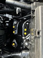
A/C1 - Yellow dots are factory bolts/holes
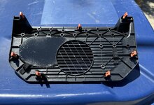
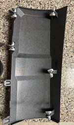
A/C2 - Mounting plate, used some stand-offs under the bolts to make it level
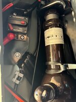
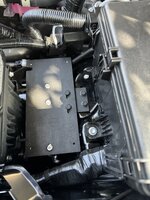
A/C3 - Compressor mounted
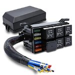
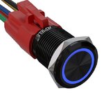
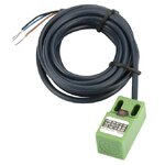
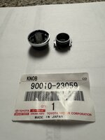
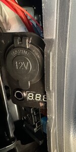
A/C4 - Switch is from "CH4X4" (cube size)
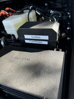
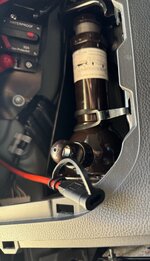
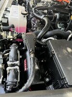
A/C5 - Air tank mounted, it's tight but it fits
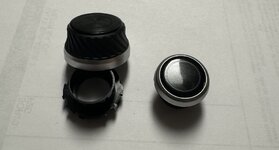
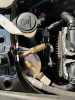
A/C6 - Chuck, pressure switch installed. I use a small tank, not for air storage volume but to take advantage of an air pressure switch. That way the compressor doesn't run non-stop. I also use a "pressure relief valve" in order to not burst the tank.
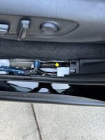
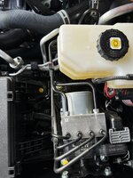
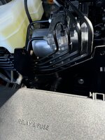
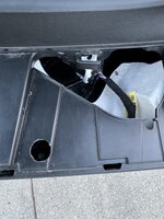
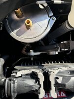
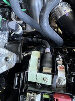
A/C 7 - Passenger side Pwr Distro box, corner cover removed showing the main feed and starter cable lugs. At the top of the pic are the ribs that I removed in order to put the extension in.
A/C 8 - Ribs removed
A/C 9 - Paper template of the new buss bar extension
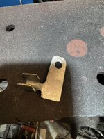
A/C 10 - Stainless Buss Bar extension, 1st bends
A/C 11 - Stainless Buss Bar extension, Finial crimp on to 6 gage wire
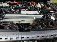
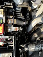
A/C 12 - Stainless Buss Bar extension, mounted
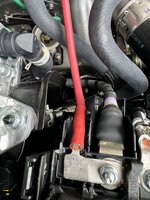
A/C 13 - Stainless Buss Bar extension, with OEM cover back in place. You can see the red 6 gage wire along the left side of the PDC, it's routed to the area in front of the air cleaner box
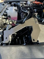
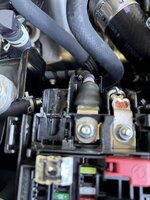
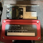
A/C 14 - Circuit Breaker and Aux Buss Bar mount
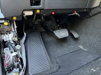
Under dash 1 - Yellow dots are bolts/screw, Red dots are tabs.
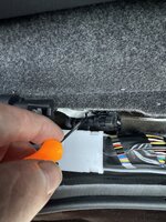
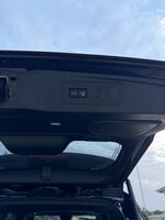
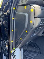
Under dash 2 - Door weather stripping must be pulled away 1st (Yellow dots) then the side panel can be pulled off (yellow dots are approx where the plastic clips are, the Blue dot is a plastic hook that must be inserted 1st when you reassemble.
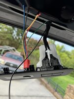
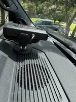
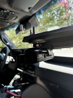
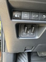
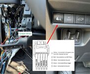
Under dash 3 - Pull straight out on the switch panel for removal. I spliced into the illumination wire (green wire coming out of the rheostat and actually spliced in where there was room).
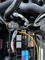
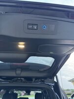
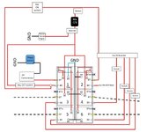
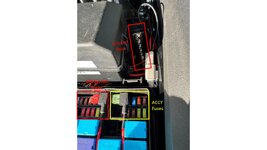
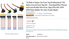
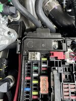
Pushed the switch and the air compressor works like it's supposed to! I used a fuse tap in an empty ACCY slot to power the Air Compressor switch (which in turn energizes the relay).
A/C1 - Yellow dots are factory bolts/holes
A/C2 - Mounting plate, used some stand-offs under the bolts to make it level
A/C3 - Compressor mounted
A/C4 - Switch is from "CH4X4" (cube size)
A/C5 - Air tank mounted, it's tight but it fits
A/C6 - Chuck, pressure switch installed. I use a small tank, not for air storage volume but to take advantage of an air pressure switch. That way the compressor doesn't run non-stop. I also use a "pressure relief valve" in order to not burst the tank.
A/C 7 - Passenger side Pwr Distro box, corner cover removed showing the main feed and starter cable lugs. At the top of the pic are the ribs that I removed in order to put the extension in.
A/C 8 - Ribs removed
A/C 9 - Paper template of the new buss bar extension
A/C 10 - Stainless Buss Bar extension, 1st bends
A/C 11 - Stainless Buss Bar extension, Finial crimp on to 6 gage wire
A/C 12 - Stainless Buss Bar extension, mounted
A/C 13 - Stainless Buss Bar extension, with OEM cover back in place. You can see the red 6 gage wire along the left side of the PDC, it's routed to the area in front of the air cleaner box
A/C 14 - Circuit Breaker and Aux Buss Bar mount
Under dash 1 - Yellow dots are bolts/screw, Red dots are tabs.
Under dash 2 - Door weather stripping must be pulled away 1st (Yellow dots) then the side panel can be pulled off (yellow dots are approx where the plastic clips are, the Blue dot is a plastic hook that must be inserted 1st when you reassemble.
Under dash 3 - Pull straight out on the switch panel for removal. I spliced into the illumination wire (green wire coming out of the rheostat and actually spliced in where there was room).
Pushed the switch and the air compressor works like it's supposed to! I used a fuse tap in an empty ACCY slot to power the Air Compressor switch (which in turn energizes the relay).
Attachments
-
 Air Compressor.jpg34.1 KB · Views: 323
 -
 Air Compressor 1.JPG310.6 KB · Views: 270
 -
 Air Compressor 2.JPG346.3 KB · Views: 264
 -
 Air Compressor 3.JPG359.6 KB · Views: 307
 -
 Air Compressor 4.JPG362.2 KB · Views: 314
 -
 Air Compressor 5.JPG250.1 KB · Views: 252
 -
 Air Compressor 6.JPG342.7 KB · Views: 169
 -
 Air Compressor 7.JPG375.5 KB · Views: 171
 -
 Air Compressor 8.JPG238.9 KB · Views: 143
 -
 Air Compressor 9.JPG310.9 KB · Views: 140
 -
 Air Compressor 10.JPG567.9 KB · Views: 129
 -
 Air Compressor 11.JPG514.4 KB · Views: 128
 -
 Air Compressor 12.JPG355.2 KB · Views: 133
 -
 Air Compressor 13.JPG407.8 KB · Views: 139
 -
 Air Compressor 14.JPG493.5 KB · Views: 147
 -
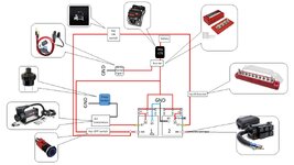 Air Comp Wiring Dia.jpg126.9 KB · Views: 137
 -
 Under dash 1.JPG438.4 KB · Views: 141
 -
 Under dash 2.JPG397.8 KB · Views: 150
 -
 Under Dash 3.jpg177.7 KB · Views: 161
 -
Interior Trim panel removal.pdf7 MB · Views: 44
Last edited: